Sometimes it's just so easy!

This is the place to post your ideas, thoughts, questions and comments as relates to general boatbuilding and reconstruction techniques and procedures (i.e. recoring, epoxy, fiberglass, wood, etc.)
Post Reply
Figment
Damned Because It's All Connected
Posts: 2846
Joined: Tue Apr 08, 2003 9:32 am
Boat Name: Triton
Boat Type: Grand Banks 42
Location: L.I. Sound

Sometimes it's just so easy!

Post by Figment »

After finally locating the proper size hose to fit the stuffing box, and then thickening the stern tube to accept this new hose (old hose was not reinforced, and was able to be hose-clamped down to size) the cutless bearing reinstallation finally happened. That propshaft went back into the coupling like butter!

I lined the two up and yelled for my buddy on the ground to "give it a little goose just to seat it", thinking that he'd need the block and mallet to drive it home. My one eye peeking through the cockpit access port was bewildered to see it slide all the way in. All boatwork should be so easy!

Of course, hours later I learned the other edge of the sword.... the previous installation must not have had the shaft so deeply installed in the coupling, because now I don't have enough space to fit a zinc between the prop and the cutless bearing!

Mr. Zinc, allow me to introduce you to my old buddy, Mr. Bench Grinder.

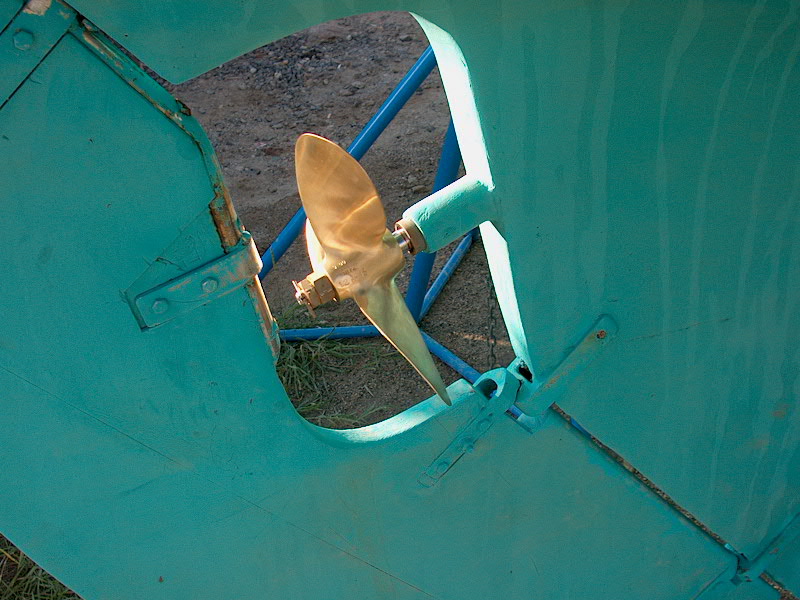
As far as I can see, the only true downside to this is that the zinc will need to come off before a prop puller will be able to take a bite, but I'm fairly certain that this was the case before anyway (see as-found pic)

Image

I figure if I'm swimming with tools for an underwater prop swap, a hex key (does no one refer to them as "allen wrenches" anymore?) for the zinc won't be much of an additional hassle.

Does anyone here think I'm nutty, and that I should back the shaft out some?
User avatar
Tim
Shipwright Extraordinaire
Posts: 5708
Joined: Tue Apr 01, 2003 6:39 pm
Boat Name: Glissando
Boat Type: Pearson Triton
Location: Whitefield, ME
Contact:

Post by Tim »

Does anyone here think I'm nutty, and that I should back the shaft out some?
Boy, you left yourself wide open there! Two separate questions, as far as I'm concerned! ;<)

Seriously, my answer is: no, do not jeopardize the seat of your shaft in the coupling, where it really counts, in order to fit a full zinc on there. It's more important to have a properly seated shaft. I believe shafts should be inserted as far as possible into the half coupling, till the shaft end is flush with the inside of the coupling. Don't you have set screws too that need to fit into the milled dimples in the shaft, through the coupling?

I don't even have a shaft zinc on Glissando, mainly because there's simply no room. Someone had a prop nut zinc that fit the Triton well...was that Bob Paterson (anyone...anyone)? I can't recall.

Image

Just curious: why are you anticipating underwater prop changes? Just planning for all possibilities in advance? I know if can be done, but it tends to be such a hassle even on land that I'd hate to do it in the water! Maybe that waterproof grease I put on the shaft will help in that respect. I'll know in 2 years when I take the whole shaft assembly apart again.

Tim
Figment
Damned Because It's All Connected
Posts: 2846
Joined: Tue Apr 08, 2003 9:32 am
Boat Name: Triton
Boat Type: Grand Banks 42
Location: L.I. Sound

Post by Figment »

Just curious: why are you anticipating underwater prop changes?
Heh. You caught me. The mentality of my powerboat heritage shines through sometimes. I'm the only sailor in the family.
As a youngster I made quite a bit of money doing underwater prop changes. During the coldwater months, particularly the spring when the waters are full of debris, the regular utterance around the club was "call that crazy Haas kid, he'll swim in anything!"
How did I get this reputation, you ask? simple... my little brother has an uncanny knack for finding lumber in the water at high speed. After a while people started noticing that my dad's boat would get towed in one weekend, and would be out running again the next with no haulout. Word of cheap child labor spreads like wildfire. My $75 fee was a fraction of haulout cost, and the wife stays happy because her dockside social life isn't interrupted. Can't put a price on domestic harmony.

Seriously, though.... Yeah, thinking toward the underwater work is really just fundamental application of Murphy's Law.

There's a single setscrew, but no dimple machined in the shaft. Should I drill one? How much thrust can an A4 realistically generate to stress that connection?

How's that 2blade prop working for you? Do you not have a reduction gear on your diesel?

I see you left your cutless bearing exposed by one vice-grip width. I left mine out by a half-width, but waxed it before installation. How critical do you think the holes forward of the bearing are? I drilled new ones to accommodate the longer bearing, but it seems to me that these will be easily obstructed by growth.
Last edited by Figment on Wed Apr 30, 2003 3:47 pm, edited 1 time in total.
dasein668
Boateg
Posts: 1637
Joined: Thu Apr 03, 2003 9:09 am
Boat Name: Dasein
Boat Type: Pearson Triton 668
Location: Portland, Maine
Contact:

Post by dasein668 »

Hey, nice catch on the prop! But I can tell you from being there first hand, its actually a 3 blade. Michigan Wheel Sailor, I think. Its just the picture he posted looks 2-bladed.

That'll teach you to be more careful with your posts Tim! hehe
Figment
Damned Because It's All Connected
Posts: 2846
Joined: Tue Apr 08, 2003 9:32 am
Boat Name: Triton
Boat Type: Grand Banks 42
Location: L.I. Sound

Post by Figment »

oh, yeah, I can see it now.... the top blade in the pic is at 12:00 and the bottom is actually at 4:00, not 6:00.
User avatar
Tim
Shipwright Extraordinaire
Posts: 5708
Joined: Tue Apr 01, 2003 6:39 pm
Boat Name: Glissando
Boat Type: Pearson Triton
Location: Whitefield, ME
Contact:

Post by Tim »

Sheesh, you guys...got to stay right on my toes here! I think it's obvious that it's a three blade, since you can see from the shadow lines that what appears to be the "lower" blade is actually turned slightly towards the camera, obviously because it's a three blade and two blades never oppose each other directly...geez, it's obvious to anyone with half a brain...

(Shut up, Tim.) hehe Just kidding, of course! It does look like a two-blade. Here's a different photo that shows it--well--differently.

Image

It's a 3-blade Michigan Sailer (yes, they use the "e", the Heathens), size 12x13. And yes--I left part of the bearing exposed for ease of gripping it later, plus I didn't do the shaft log modification to allow the use of a full-length bearing--so I wanted as much bearing as possible, given the limitations of the shaft log.

I don't have the holes at the forward end. Guess that shows how important I think they are.

The dimples are there to hold the shaft against sliding backwards out of the coupling, not to resist the torgue of the engine--that's the job of the keyway. You do have a keyway, right?

Tim
Figment
Damned Because It's All Connected
Posts: 2846
Joined: Tue Apr 08, 2003 9:32 am
Boat Name: Triton
Boat Type: Grand Banks 42
Location: L.I. Sound

Post by Figment »

oh, yeah, there's a keyway and key for the torque alright. That's why I wonder about the real need for the dimple, which therefore is only responsible for resisting longitudinal thrust.
dasein668
Boateg
Posts: 1637
Joined: Thu Apr 03, 2003 9:09 am
Boat Name: Dasein
Boat Type: Pearson Triton 668
Location: Portland, Maine
Contact:

Post by dasein668 »

Regarding the set screw/dimple thing on the shaft: I'd say, you are probably right, its probably not going to come loose. On the other hand, theres guite a bit of vibration there, and I guess it is conceivable that it could work its way out. I figure its just a little extra insurance. I have it on mine, but I didn't drill out the new set screw so that I could wire it in place, like the old installation had. I guess I wasn't *that* worried about it! Plus, when I checked halfway through the season, the set screw was still tight.

That's my 2 cents on the subject....
David

Propeller shaft locking nuts...

Post by David »

I noticed in the two photos in this thread that it *appears* that the thicker nut is against the propeller hub in the first pic, but the thinner nut is against the hub in the second pic. Perhaps they are situated the same and just look different. My question is this: which is correct (or is there a truly correct arrangement of the the two sized nuts)?

I had always learned that the thin nut goes against the hub first; then the thicker nut goes on. The load is taken by the after nut; the thicker nut capable of taking more torque than the thinner nut. Having said that, I can't remember for the life of me why this is true.

Can anyone confirm this or argue it? Am I making this all up?? What does our resident surveyor say on the subject?

David
User avatar
Tim
Shipwright Extraordinaire
Posts: 5708
Joined: Tue Apr 01, 2003 6:39 pm
Boat Name: Glissando
Boat Type: Pearson Triton
Location: Whitefield, ME
Contact:

Post by Tim »

Technically, the small nut should go on first (against the prop hub), with the large nut afterwards.

The two pictures of my boat are indeed different: the first picture (the one showing the side view of the prop) is actually a more recent photo than the other one, in which the large nut is against the hub. I installed that wrong when I first installed the prop during my repower in 2001; I later replaced them in the proper manner last fall when I took apart the whole shaft, prop, coupling, etc. for maintenance. So as it stands now, the small nut is against the hub, with the larger lock nut outboard.
---------------------------------------------------
Forum Founder--No Longer Participating
David

Locking shaft nuts

Post by David »

Thanks for the info Tim. Can you tell me why the thinner nut is supposed to go first against the hub?
User avatar
Tim
Shipwright Extraordinaire
Posts: 5708
Joined: Tue Apr 01, 2003 6:39 pm
Boat Name: Glissando
Boat Type: Pearson Triton
Location: Whitefield, ME
Contact:

Post by Tim »

David,

The theory is that the outer (larger) nut, when tightened against the already-installed inner (smaller) nut, actually unloads the small nut when properly tensioned, which therefore means that the full-thread nut is carrying the tension and load.

I think in practice, it probably doesn't matter a whit. But this is the supposed theory.
---------------------------------------------------
Forum Founder--No Longer Participating
Post Reply