Wiring diagram review

Ask a question...get an answer (or two).
Post Reply
User avatar
Munster
Bottom Paint Application Technician
Posts: 13
Joined: Tue Feb 02, 2010 10:22 am
Boat Name: Nuala
Boat Type: Tartan 27

Wiring diagram review

Post by Munster »

I'm in the process of upgrading and adding to the electrical systems on my boat and wanted to run the diagram for the changes I'm making past the experts before I'm finished.

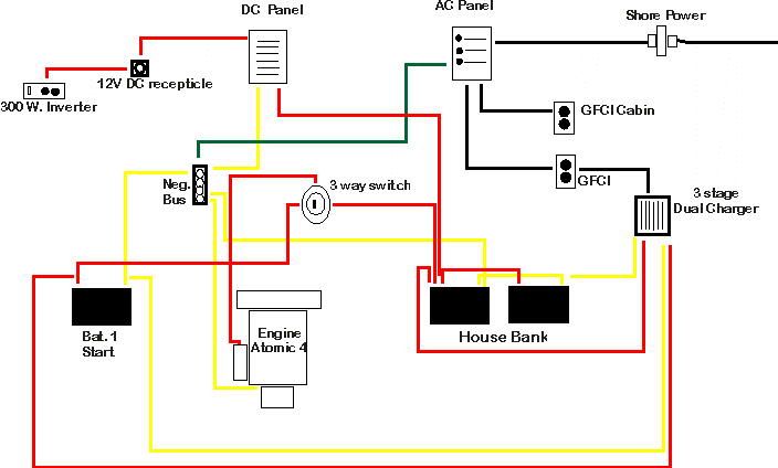
When I aquired the boat, it had a single start Battery wired directly to the engine, feeding a DC distribution panel. There was no AC power. While my power needs are relatively light, I wanted to add shore power capability and a battery charger, as well as adding a house bank for greater capacity while cruising.

What I have added so far is a 3 circuit AC panel, a house bank of two deep cycles in parrallel, a 3 way battery switch, a GFCI recepticle for cabin use, a GFCI recepticle to plug a dual battery charger into and a DC recepticle to plug an inverter into.

The only other change I'm still thinking about is adding a Galvanic Isolator between the shore power recepticle and the AC panel but since I'm not going to leave the boat plugged into shore power for extended periods, I'm wondering if this is overkill.

Btw, the pos. feeds off of the battery charger to the batteries both have in-line fuses not shown on the diagram. The AC circuits are on 15 amp breakers and are wired with Marine tinned 14 Ga AWG, the primary feed to the AC panel with 10 Ga. Marine AWG.

I'd appreciate it if people would take a look at the wiring diagram and tell me what I'm missing or if they would change anything,

Image
Jim Sweeney
Tartan 27 #487 "Nuala"
Traverse City, MI
Ryan
Skilled Systems Installer
Posts: 223
Joined: Wed Aug 17, 2005 2:14 pm
Location: NE GA

Re: Wiring diagram review

Post by Ryan »

Make sure the wire runs from the batteries are fused at the batteries, not at the charger, panel, etc. As far as the isolator, that is a personal decision, but they are cheap insurance against stray current corrosion which can be quite fast acting.

FWIW, I would wire the alternator directly to the house bank and bypass the switch. No worries of forgetting to leave the switch in the correct position for charging, and no chance of damaging alternator diodes by switching to or through the "OFF" position while the engine is running. Then connect the panel to the third terminal (COMMON) of the switch so you can easily cut power off from the panel when you need to work on it or when you leave the boat.

Also keep in mind that a 300W inverter puts quite a load on a 12V plug in connector (and the associated wiring), upwards of 30+ amps if fully loaded.
Hirilondë
Master of the Arcane
Posts: 1317
Joined: Thu Dec 28, 2006 8:50 am
Boat Name: Hirilondë
Boat Type: 1967 Pearson Renegade
Location: Charlestown, RI

Re: Wiring diagram review

Post by Hirilondë »

Good stuff Ryan. I agree with all of the modifications. My only question would be: How does he charge the start battery while cruising if the alternator goes to the house? I suppose he could switch the battery switch to both and get some charge that way.
Dave Finnegan
builder of Spindrift 9N #521 'Wingë'
--------------------------------------------------------------------------------------------------------------------------------------------------------------------
Gresham’s Law of information: Bad information drives out good. No matter how long ago a correction for a particular error may have appeared in print or online, it never seems to catch up with the ever-widening distribution of the error.
Ryan
Skilled Systems Installer
Posts: 223
Joined: Wed Aug 17, 2005 2:14 pm
Location: NE GA

Re: Wiring diagram review

Post by Ryan »

You're correct, you would just switch to "both" or "combine" to charge the start battery, but it is not something that would need to be done often as the start battery loses very little amp-hours from starting and the shore power charger would take care of it when at the dock. For me, the best solution would be an echo charger that took care of charging the start battery whenever the house bank was being charged without the need to switch anything, but that means another link in the chain.

FWIW, the engine could be started with the house bank as a matter of routine and the start battery would only be used in the event the house bank has been drained. Lots of ways to skin the cat!
Maine Sail
Skilled Systems Installer
Posts: 243
Joined: Fri Feb 24, 2006 10:47 am
Location: Casco Bay
Contact:

Re: Wiring diagram review

Post by Maine Sail »

Hirilondë wrote:Good stuff Ryan. I agree with all of the modifications. My only question would be: How does he charge the start battery while cruising if the alternator goes to the house? I suppose he could switch the battery switch to both and get some charge that way.
You can simply add a digital Echo Charger or Balmar Duo Charger or a Blue Seas or Yandina voltage sensitive relay then all you do is switch to HOUSE when you get to the boat and switch to OFF when you leave. No need on a small boat to use the start battery if maintaining your bank properly. The Blue Seas ACR is about $65.00 and well worth the expense.

Don't forget that you'll want a breaker interrupting both hot (black) and neutral (white) wires for your shore power inlet if the WIRE is longer than 10 feet from the male inlet plug to the breaker on the AC panel. This is not line of sight distance but wire length.


11.12.2.9.3. If the location of the main shore
power disconnect circuit breaker is in excess of 10 feet
(three meters) from the shore power inlet or the
electrical attachment point of a permanently installed
shore power cord, additional fuses or circuit breakers
shall be provided within 10 feet (three meters) of the
inlet or attachment point to the electrical system of the
boat. Measurement is made along the conductors.


P.S. You might melt the 12V socket running a 300W inverter off of it. Did this in my car even though I knew I should not have. If the wires to your socket are big enough for the laod you might be okay but I always prefer to hard wire inverters..


P.S.S. Go with an ACR or Echo Charger then you can get away with a single output shore charger like those from Iota which are very rugged, very reliable and quite reasonably priced. Just run all charging sources to the house bank and let the ACR or Echo take care of the rest..
-Maine Sail

Canadian Sailcraft 36T
Casco Bay, ME
http://www.marinehowto.com
User avatar
Munster
Bottom Paint Application Technician
Posts: 13
Joined: Tue Feb 02, 2010 10:22 am
Boat Name: Nuala
Boat Type: Tartan 27

Re: Wiring diagram review

Post by Munster »

Thank you everyone for the input, much appreciated.

The DC recepticle is wired with 10 GA wire and the run is only 15" from the panel, seems like that should be enough to prevent melting anything with a 300 W inverter, should'nt it?

The charger I have is a dual output, 3 stage, with seperate outputs to each bank, it splits the charge between the two, It's wired directly to each bank, not to the battery switch, with fused wires, so when plugged into shore power, both batteries will be charging, no need to switch the battery switch to both.

As far as charging both batteries with the alternator output, it seems to me to make more sense just to run the output to the house bank. The start battery will only be used for starting, never for supplying anything wired to the DC panel and it will get topped off whenever I plug into shore power. Seems unlikely that I would run it down just by using it for starting. My atomic 4 has the older style alternator which I believe only puts out around 30 amps, I just don't use the engine very much when away from shore power and I have a Honda 2000 portable gen that I will take with if cruising for any extended time away from port. It seems like it would be easier to plug that into the shore power recepticle and let the AC charger replenish the depleted house bank if need be, instead of motoring for extended periods of time just to charge batteries with the alternator output. Power needs are pretty modest, only lights (some of which are LED's), blower, bilge pump, radio and recharging laptop, Kindle & cell phone, so the Amp hours needed are pretty minor. No heat, refridgeration or any other heavy duty draws that I can think of.

Distance from Shore Power recepticle to AC panel is 4 feet, I specifically located it as close as I could to minimize the wire run.

Ryan, when you say fuse the battery wires, are you talking about the primary 4 Ga feed from the batteries to the 3 way switch? If so, what size fuse would you use, it seems it would have to be pretty large (200 amp?) to allow juice to get to the starter without melting the fuse. If you are just talking about the smaller feeds to the DC panel, the bilge pump and the pos. inputs from the charger, those are already fused with 20 amp in-line fuses.

Thanks again, everyone for the help.
Jim Sweeney
Tartan 27 #487 "Nuala"
Traverse City, MI
Ryan
Skilled Systems Installer
Posts: 223
Joined: Wed Aug 17, 2005 2:14 pm
Location: NE GA

Re: Wiring diagram review

Post by Ryan »

Munster wrote: Ryan, when you say fuse the battery wires, are you talking about the primary 4 Ga feed from the batteries to the 3 way switch? If so, what size fuse would you use, it seems it would have to be pretty large (200 amp?) to allow juice to get to the starter without melting the fuse. If you are just talking about the smaller feeds to the DC panel, the bilge pump and the pos. inputs from the charger, those are already fused with 20 amp in-line fuses.

Thanks again, everyone for the help.
Strictly speaking from an ABYC perspective, the wire from the battery directly to the starter does not need to be fused. That said, I prefer to fuse EVERY wire connected from the battery. Starter wires can chafe and short the same as any other. Fusing the starter wire is for short circuit protection and as such the value of the fuse size isn't as critical as it would be for an overload situation. I would probably shoot for 175A fuse knowing that the starter for an A4 shouldn't be very power hungry. All other feeds from the battery should be fused, at the battery, and sized to protect the wire, no exceptions.

One thing that stands out is you say you have the feed to the panel fused with an inline 20A fuse. Since that fuse has to carry the combined current of everything fed from the panel, 20A may not be enough as the inverter itself can draw more than 20A.
Post Reply